


Troubleshoot Intermittent High RPM Alarms on Evinrude V6 Loopers (VRO Disconnected)
- Understanding the Warning Horn After VRO Disconnection
- Tachometer Signal Distortion Causes False Alarms
- Step-by-Step Electrical Isolation Procedure
- Testing the Alarm Horn and Sensor Inputs
- Confirming Cooling System Function
- System Check Gauge vs. Analog Tachometer
- False Alarm vs. Real Alarm Comparison
- Testing the Voltage Regulator and Stator (Static Resistance Test)
- Bypass Test to Isolate Boat Wiring from Engine Wiring
- Testing the Alarm Horn Directly
- Premix Ratio and Fuel Delivery Check
- What to Do If All Tests Pass
- Quick Reference Specs
- FAQ: VRO Disconnect and Alarm Wiring


If you're running an Evinrude V6 looper with the VRO disconnected and getting intermittent alarms at high RPM, you're chasing electrical gremlins nine times out of ten. The engine isn't actually over-revving. Something in the tach circuit, wiring harness, or alarm logic is sending a false signal.
This guide applies to 1986–2001 V6 loopers running premix after VRO removal. You'll need a digital multimeter.
Understanding the Warning Horn After VRO Disconnection

When you pull the VRO and run premix, you've eliminated the oil-related alarms. What's left are overheat and fuel-restriction warnings. The horn uses different tones: steady for overheat or fuel restriction, intermittent chirping for low oil (which should be disabled after VRO removal).
The tan warning wires from the old VRO oil sensors must be capped and secured. If a loose tan wire shorts to ground intermittently, the horn will chirp randomly. Check that every disconnected VRO tan wire is wrapped and zip-tied away from the block.
Tachometer Signal Distortion Causes False Alarms
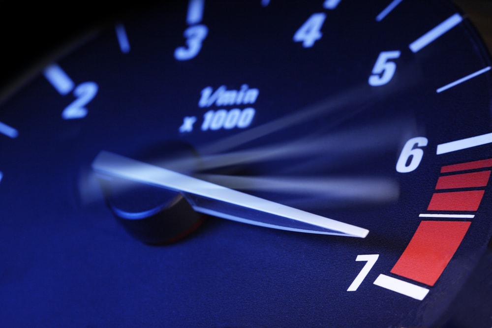
The most common culprit is a bad voltage regulator or failing stator. The grey tach wire runs from the stator through the rectifier-regulator to your gauge. When the regulator fails, it sends a noisy, spiking signal. Your dash tach jumps to 6,000 or 7,000 RPM while the engine is actually turning 4,500. The ignition module sees what it thinks is an over-rev and triggers the horn.
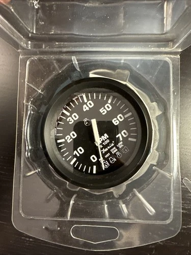
To confirm this, run the engine and watch your tach. If the needle bounces or pegs out while the engine note stays steady, you've found it. Cross-check with a shop tachometer wired directly to the grey signal wire at the engine harness. If the shop tach reads normal and your dash tach reads high, replace the voltage regulator.
Stator output specs for V6 loopers:
At idle (around 1,000 RPM), stator output on the grey wire should be roughly 18–22 VAC. At 3,000 RPM, expect 40–50 VAC. Anything wildly erratic or pegged at zero indicates stator failure. Use a multimeter with a peak voltage adapter for accurate readings on the grey wire while the engine runs.
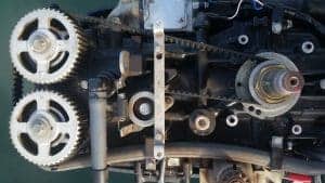
A failing stator physically looks like this: potting material drips onto the block below the flywheel, and the windings smell burned if you pull the flywheel. The stator is bolted under the flywheel with three or four screws; remove the flywheel with a puller (never pry or hammer it) to inspect. For detailed steps on removing and inspecting components like the flywheel and water pump, you can refer to our Johnson/Evinrude Outboard Water Pump Replacement Guide.
Step-by-Step Electrical Isolation Procedure
Start at the battery. Clean and tighten both terminals. On the V6 block, the main engine ground is a braided strap bolted near the starter solenoid. Remove it, wire-brush both the terminal and the bolt hole, reinstall, and torque to snug (don't strip the aluminum threads).
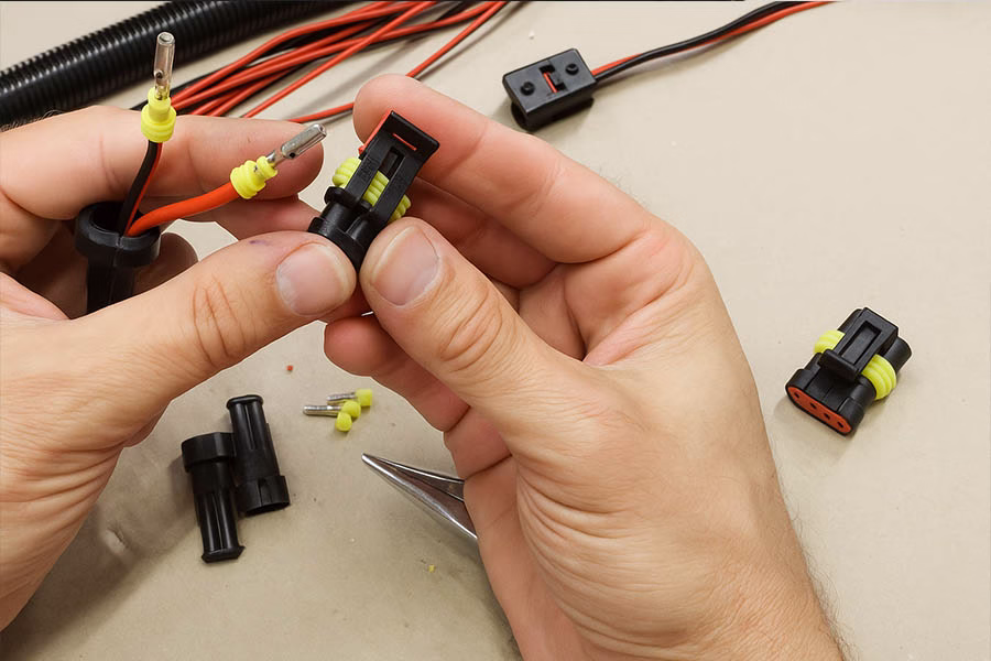
Inspect every visible connector in the main engine harness. Look for green or white corrosion on the pins. Disconnect each one (battery off first), spray with electrical contact cleaner, let it dry, then apply dielectric grease and reconnect. Pay close attention to the round multi-pin connector where the boat harness meets the engine harness—this is a common failure point in saltwater environments.
Check the tan-wire blocking diodes in the engine harness. On V6 loopers, each sensor (overheat, fuel restriction) has a blocking diode in-line on its tan warning wire. When a diode fails open, that sensor can't trigger the horn. When it fails shorted, it allows the tach signal to bleed backward into the alarm circuit, creating phantom alarms. To test: disconnect the tan wire at the sensor, measure diode forward voltage (should be around 0.6V in one direction, infinite resistance in reverse). Replace the entire harness section if the diode is shorted.
Safety precaution: The stator produces high AC voltage. Do not touch the grey wire or stator leads while the engine is running. Wrap all test lead clips in electrical tape to prevent accidental contact with the block.
Testing the Alarm Horn and Sensor Inputs
Ground the tan wire at the horn with a jumper wire (battery connected, key on, engine off). The horn should sound immediately. If it doesn't, check the horn's power supply: the purple wire should have 12V when the key is on. If you have 12V and the horn still won't sound when grounded, replace the horn.
Now test each sensor individually. Locate the overheat sensor—it's a brass switch screwed into the cylinder head near the number-six cylinder. The sensor is roughly the size of a spark plug and has a single tan wire. Disconnect the tan wire, turn the key on, and briefly touch the wire to ground. The horn should sound. If it does, the wiring from the sensor to the horn is good.
To test the sensor itself, remove it from the head (10mm deep socket). Heat it in a pot of water on a stove. At roughly 200°F, the internal switch should close and create continuity to ground. Measure continuity with your multimeter while heating. If it never closes, replace the sensor.
Fuel-restriction sensors (if equipped) are usually mounted on the fuel rail or primer bulb bracket. They trigger when vacuum in the fuel line exceeds a set point (usually around 2–3 psi vacuum). To test: disconnect the tan wire, ground it, confirm the horn sounds. Then reconnect it and crimp the fuel line partially while running the engine at 3,000 RPM. The horn should sound within a few seconds. If it doesn't, the sensor or vacuum switch is dead. For more on identifying fuel issues that affect performance, check out Outboard Bogging Down? Troubleshooting Low Power, RPM Fluctuations & Fuel Issues.
Confirming Cooling System Function
Even though you're chasing an electrical fault, always rule out a real overheat. A marginal water pump or sticky thermostat can cause intermittent high-temperature spikes at higher RPM that trigger the overheat sensor legitimately.
Check the pee stream at idle. It should be a steady pencil-thick flow. Under throttle, it may thin out slightly but should never dribble or stop. If the stream is weak at idle and disappears above 3,000 RPM, pull the lower unit and replace the water pump impeller. For detailed replacement instructions and to understand more about water pump components, visit our Evinrude Water Pump Impeller collection and see our Signs Your Outboard Impeller Needs Replacement guide.
Use an infrared thermometer on the cylinder heads while running at 3,000 RPM on the hose (or better, on the water under load). Temps should be 140–160°F. Anything above 180°F indicates restricted cooling passages or stuck thermostats. The thermostats are located in the cylinder head covers; remove the covers (six bolts each, 10mm socket) and pull the stats. Drop them in boiling water—they should open fully. If they don't, replace them. Some helpful thermostat maintenance tips are available in Thermostat Maintenance: Keeping Your Outboard Running Cool and Testing a Yamaha Outboard Thermostat in Hot Water.
Blocked cooling passages happen on older engines. Pull the thermostat covers and inspect the poppet valve (a spring-loaded plunger in the head). If it's caked with salt or carbon, it won't release pressure correctly, causing localized hot spots. Clean it with vinegar and a wire brush.
System Check Gauge vs. Analog Tachometer
V6 loopers built before 1990 typically used a simple analog tach and a separate horn. From 1990 onward, some models came with the System Check gauge—a four-light panel showing overheat, no oil, low oil, and check engine. The alarm logic is different.
Analog tach / horn-only systems:
The horn sounds steady for overheat or fuel restriction. Intermittent chirping indicates low oil or VRO fault (should be disabled after VRO removal).
System Check gauge (four-light) systems:
The lights correspond to specific faults. A red overheat light stays on solid. A yellow check-engine light blinks for fuel restriction or over-rev. The horn still sounds, but the light pattern tells you which circuit triggered. If you have a System Check gauge and the yellow light blinks at high RPM without the red light, you're looking at a tach signal fault, not overheat.
False Alarm vs. Real Alarm Comparison
False high-RPM alarm:
Dash tach reads 6,000+ RPM, engine note steady, no loss of power, pee stream strong, cylinder head temps normal (140–160°F), alarm sounds intermittently only at higher throttle settings.
Real overheat alarm:
Dash tach reads normal, engine note rough or misfiring, steam from pee stream, cylinder head temps above 180°F, alarm sounds steady and does not stop until engine cools.
Real fuel-restriction alarm:
Engine bogs or surges under load, fuel bulb collapses and stays soft, primer bulb difficult to pump, alarm sounds steady at sustained high RPM, pee stream normal, temps normal.
Testing the Voltage Regulator and Stator (Static Resistance Test)
Disconnect the grey tach wire at the engine harness. Set your multimeter to ohms (resistance). Measure from the grey wire terminal to engine ground. You should read infinite resistance (open circuit). If you read continuity or low resistance (below 100 ohms), the stator winding is shorted to ground. Replace the stator.
Now measure stator AC output while running. Reconnect the grey wire. Back-probe the grey wire at the gauge or at the engine harness with your multimeter set to AC volts. Start the engine and note voltage at idle, 2,000 RPM, and 3,000 RPM. Write down the numbers. Compare to the spec range I listed earlier. If voltage is erratic, spikes, or reads zero at any RPM, replace the stator and rectifier-regulator together (they often fail as a pair).
Physical location of the stator: It's under the flywheel. You'll need a flywheel puller (OMC part number or aftermarket equivalent) and a strap wrench to hold the flywheel while you remove the center nut (use a breaker bar; it's torqued to roughly 100 ft-lbs). Once the flywheel is off, the stator is visible as a ring of copper windings bolted to the powerhead with three screws. Unplug the connector, remove the screws, lift the stator off.
Bypass Test to Isolate Boat Wiring from Engine Wiring

To confirm whether the fault is in the boat harness or the engine harness, run a temporary jumper from the engine's grey tach wire directly to a portable shop tach, bypassing the boat's gauge and wiring entirely. Do the same for the alarm horn: run a new 12V power wire and a new ground wire directly from the battery to a test horn, then jumper the tan sensor wires to the test horn.
Run the engine and watch for the alarm. If the test tach reads correctly and the test horn stays silent, the problem is in the boat's harness (corroded dash connections, bad gauge, or broken wire run). If the test equipment still shows the fault, the problem is in the engine harness or a sensor.
Testing the Alarm Horn Directly

Remove the horn from its mount (usually two screws on the transom bracket). It has two wires: purple (12V power when key is on) and tan (ground trigger). With the horn removed and the battery connected, touch the tan wire terminal to battery negative. The horn should sound immediately. If it doesn't, and you've confirmed 12V on the purple wire, the horn is dead. Replace it.
Premix Ratio and Fuel Delivery Check

Running the wrong oil ratio won't directly cause an alarm, but a lean fuel mixture can cause detonation that spikes cylinder temps momentarily, triggering the overheat sensor intermittently. Evinrude V6 loopers with VRO removed should run 50:1 premix (2.6 oz of TCW3 oil per gallon of fuel).
Check for fuel restriction even if you don't have a fuel-restriction sensor. Install a vacuum gauge in-line on the fuel hose between the tank and the engine. At wide-open throttle, vacuum should not exceed 2 psi. Higher vacuum indicates a clogged anti-siphon valve, kinked fuel line, or dirty fuel filter. Replace the inline fuel filter and inspect the anti-siphon valve at the tank pickup. You can find high-quality Evinrude Fuel Filter replacement parts and vacuum gauges in our selection.
What to Do If All Tests Pass
If you've confirmed good grounds, clean connections, correct tach signal, working sensors, and normal cooling, but the alarm persists, replace the ignition module (power pack). The power pack interprets signals from the stator and sensors. Internal failures can cause it to misread normal signals as fault conditions. This is rare but happens on high-hour engines. The power pack is bolted to the side of the powerhead under a plastic cover (four screws, 8mm socket). Replacement is straightforward—unplug the two connectors, unbolt, swap, reconnect.
To explore and order the necessary Evinrude outboard motor parts for repairs including power packs, stators, and sensors, visit our parts collections.
Quick Reference Specs
- Stator AC output (grey wire): 18–22 VAC at idle, 40–50 VAC at 3,000 RPM
- Overheat sensor closing temp: ~200°F
- Normal cylinder head temp under load: 140–160°F
- Fuel vacuum at WOT: <2 psi
- Premix ratio (VRO removed): 50:1 (2.6 oz oil per gallon)
- Spark plug gap: 0.040"
FAQ: VRO Disconnect and Alarm Wiring
Q: I disconnected the VRO oil pump. Do I need to do anything to the wiring?
A: Cap and secure all tan warning wires from the oil reservoir and VRO pump. Do not let them touch ground. Leave the overheat and fuel-restriction tan wires connected.
Q: My alarm sounds at startup for two seconds, then stops. Is that normal?
A: Yes. Most System Check gauges run a self-test at key-on. If the alarm sounds briefly and the engine starts and runs normally, ignore it.
Q: The alarm sounds steady at idle but stops when I throttle up. What is that?
A: That's usually a grounding problem or a failing sensor that loses contact under vibration. Check sensor connections and grounds first.
Q: Can I just disconnect the horn to stop the noise?
A: No. The alarm is there to protect the engine. Disconnecting it means you won't know when the engine is genuinely overheating or starving for fuel.
Flush your cooling system with fresh water after every saltwater outing. This prevents salt buildup in the thermostat housings and poppet valve, which is the number-one cause of intermittent overheat alarms on older engines. For more tips on water pump and thermostat maintenance to ensure a reliable cooling system, see our collection on Cooling System parts.
For all your marine parts needs, including specialized components for Evinrude engines, check out the full range at JLM Marine.