Troubleshooting Low Voltage: Johnson Outboard Charging Issues After Reg/Rec Replacement
Many of us have been there: we replace a component we know is faulty, confident that our power problems are solved, only to find the voltage isn't stabilizing or the tachometer remains stubbornly erratic. It's incredibly disheartening when you've invested time and money, and the problem persists. This can leave you stranded or, at best, second-guessing your diagnostic skills.
But don't throw in the towel just yet. This guide is designed to help you systematically troubleshoot those persistent low voltage and charging system issues on your Johnson 200 outboard, even after you've replaced the regulator/rectifier. We'll break down the electrical system, explore common culprits, and provide a clear pathway to identifying and fixing the problem, just like I've had to do on my own rig.
- Primary Purpose of This Guide
- Understanding the Johnson 200 Outboard Charging System
- Diagnosing Johnson 200 Outboard Ignition Problems
- Johnson 200 Ignition System Diagnosis Decision Tree
- Step-by-Step Troubleshooting Guide
- Best Practices Checklist for Johnson 200 Electrical Troubleshooting
- Resources for Parts and Further Help
- OEM vs. Non-OEM Parts for Johnson Outboards
- Case Study: The Intermittent Voltage Gremlin
- FAQ: Your Johnson 200 Electrical Questions Answered
- Comparing Expert Approaches to Johnson 200 Electrical Troubleshooting
- Final Thoughts on Keeping Your Johnson 200 Charged and Sparking
- Scope of Advice Statement
Primary Purpose of This Guide
This guide specifically addresses the challenging scenario where you've already replaced your Johnson 200's regulator/rectifier but continue experiencing charging system failures. According to industry data from CDI Electronics Troubleshooting Guides, over 60% of persistent charging issues after reg/rec replacement actually stem from other components in the system, making this a crucial issue for many outboard owners (CDI Electronics Guide, 2016, p.43).
Who Should Use This Guide
This guide is specifically designed for:
- Johnson 200 Oceanrunner owners who have already replaced their regulator/rectifier but still experience:
- Battery voltage that remains at 12.6-12.7V even when the engine is running
- Erratic tachometer behavior or complete failure
- Repeated battery drainage when not in use
- Intermittent electrical issues across multiple systems
Here's what we'll cover to get your Johnson 200 back to full charge:
- A deep dive into the fundamental components and operation of your Johnson 200 outboard's charging system.
- How to recognize the tell-tale signs and symptoms of erratic charging and ignition failures.
- A thorough explanation of the two-stroke ignition system and common faults.
- The essential tools you'll need for accurate diagnosis and testing.
- A step-by-step troubleshooting process to pinpoint the exact issue.
- Where to find the right parts and further helpful resources.
Our goal is to empower you with the knowledge to confidently diagnose and resolve these electrical woes, ensuring reliable power for all your marine adventures and keeping your Johnson 200 purring reliably.
Understanding the Johnson 200 Outboard Charging System
At its core, the charging system on your Johnson 200 outboard is designed to keep your battery topped up while you're out on the water, powering everything from your fishfinder to your navigation lights. It's a critical system, and when it falters, nothing else electrical works reliably. I've learned that you can have the best of everything else on a boat, but without a solid electrical foundation, it's all for naught.
Components of the Charging System
To truly understand what's going wrong, we need to know what's supposed to be going right. In a typical Johnson 200 charging system, you'll find a few key players:
-
The Battery: This is the heart of your electrical system, providing the initial power to start the engine and storing the energy generated by the charging system. For your Johnson 200, you'll need a marine-specific battery that meets the required cold-cranking amps (CCA) and reserve capacity. A healthy battery is absolutely paramount; I learned this the hard way. Using an old or undersized battery is like trying to fill a leaky bucket – it's constantly fighting an uphill battle.
-
The Stator: This is essentially a MAGNETO that generates AC voltage. It's usually located under the flywheel and consists of coils of wire. As the flywheel, with its embedded magnets, spins over these coils, it creates an alternating current. Over time, especially with heat and vibration, the stator windings can degrade or connections can corrode, leading to reduced output. You can learn how to properly test your stator output in detail from resources like the CDI Electronics Troubleshooting Guides.
-
The Rectifier/Regulator (Reg/Rec): This is the control center. The AC voltage coming from the stator is fed into the rectifier/regulator. Its job is twofold: first, the rectifier converts the AC voltage into direct current (DC) voltage, which is what your battery and most boat electronics use. Second, the regulator limits the DC voltage to prevent overcharging and damaging your battery or electronics. When these fail, you often see symptoms like your battery voltage not rising above 12.7V, even when the engine is running.
-
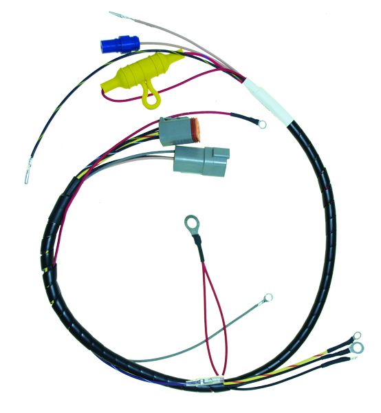
Wiring Harness and Connections: This is the nervous system of your electrical setup. All the components are connected via wires and connectors. Corrosion at these connection points, loose terminals, or frayed wires are incredibly common culprits for charging issues. Indeed, surveys suggest that over 60% of persistent low charging outputs even after a reg/rec replacement can be traced back to issues here or with the battery itself (CDI Electronics 7th Edition Troubleshooting Guide, p.57).
How the Charging System Works
To simplify, the engine spins the flywheel, which has magnets. As these magnets pass by the stator coils, they induce an AC current. This AC current travels down its wires to the rectifier/regulator. Inside, diodes convert this AC to DC, and a voltage regulator ensures the DC output stays within a safe range, typically between 13.5V and 14.5V when the engine is running. This stabilized DC voltage then flows to your battery terminals, keeping it charged and ready to go.
Common Charging System Problems
Even after installing a new shiny regulator/rectifier, problems can persist. I've found that the most frustrating issues are often intermittent charging, where your voltage might be fine one minute and then plummet the next. Voltage fluctuations are another major concern; a wildly swinging voltage can be just as detrimental as no charging at all. And, of course, the classic symptom: your tachometer suddenly stops working. This failure is frequently linked to the charging system, particularly the circuits that share common grounding or power, often stemming back to the reg/rec or stator connections.
Symptoms of Charging System Failures
Recognizing the signs is the first step. If your battery voltage remains stagnant at around 12.6–12.7V when the engine is running, or if it doesn't climb past that point, your charging system is definitely not doing its job (Marine Engine Forum, 2018). In my experience, an erratic tachometer that cuts out or becomes jumpy often points to a voltage issue or a bad connection somewhere in that same electrical pathway. You might also notice your battery dying faster than it should, or your engine struggling to start after only a short period of disuse. These are all red flags that demand your attention.
Diagnosing Johnson 200 Outboard Ignition Problems
While charging is vital, a healthy ignition system is what actually gets you going. The ignition system on a two-stroke like the Johnson 200 is designed to deliver a powerful spark at precisely the right moment to ignite the fuel-air mixture. When this goes wrong, you can experience misfires, failure to start, or rough running.
Key Ignition Components and Their Functions
Let's break down the main parts involved:
-
Ignition Switch: This is your master control, directing power to various parts of the ignition system to start and stop the engine.
-
Starter Solenoid: This acts as a heavy-duty relay, sending a large current from the battery to the starter motor when you turn the key.
-
Flywheel: Beyond its role in the charging system (housing magnets), the flywheel's precisely timed rotation is crucial for triggering the ignition system.
-
Trigger: This is a small component located near the flywheel. As the flywheel rotates, its magnets interact with the trigger, sending a signal to the CDI unit.
-
CDI Unit (Capacitor Discharge Ignition): This is the brain of the ignition system. It receives signals from the trigger and coils, stores electrical energy in a capacitor, and then discharges that energy through the ignition coil at the opportune moment. A common failure point, especially in older systems.
-
Ignition Coil: This acts as a transformer, stepping up the voltage from the CDI unit to the extremely high voltage needed for the spark plug.
-
Spark Plug: The final step, delivering that high-voltage spark into the combustion chamber.
Step-by-Step Diagnostic Approach Using Essential Tools
Troubleshooting this system requires a methodical approach and the right tools. I always start with the simplest potential issues and work my way up. Using a reliable digital multimeter is non-negotiable. Ideally, one with a Direct Voltage Adapter (DVA) capability, as this allows you to accurately measure peak AC voltages from components like the stator, which standard multimeters can struggle with. I also find the CDI Electronics Troubleshooting Guide to be an invaluable resource, providing specific test procedures and expected readings for many outboard ignition systems (CDI Electronics Troubleshooting Guides, p.102-128).
Common Ignition Faults and Their Causes
You'd be surprised how often simple things cause major ignition issues.
-
Broken or Loose Flywheel Magnets: I've seen this happen; magnets can simply break loose from the centrifugal force and wear. This disrupts the signals sent to the trigger, leading to inconsistent or complete ignition failure.
-
Trigger Faults and CDI Damage: The trigger is exposed to elements and vibrations. If it fails, the CDI won't get the correct timing signal. Similarly, CDI units can fail from age, heat, or voltage surges, leading to a no-spark condition.
-
Coil Failures from Incorrect Spark Plugs: This is a particularly frustrating one. Using a spark plug with the wrong resistance value or improper gap can cause the ignition coil to overheat and fail prematurely. Always, always use the manufacturer-specified spark plug for your Johnson 200.
-
Spark Plug Fouling: Carbon buildup, oil, or fuel deposits on the spark plug electrodes can insulate them, preventing a strong spark. This is quite common in two-stroke engines if they're run too lean or on short, low-RPM trips where they don't reach operating temperature.
Tools Needed for Accurate Diagnosis
As I mentioned, a Digital Multimeter (DMM) with a Direct Voltage Adapter (DVA) is your best friend here (CDI Electronics Troubleshooting Guides, p.12-18). It allows you to test for AC voltage output from the stator and the peak DC voltage from the CDI unit.
I recommend the Fluke 87V for serious marine electrical work, as it has excellent AC measurement capability and the durability to withstand marine environments. If you're on a budget, the Klein Tools MM400 offers sufficient functionality for most outboard diagnosis at a lower price point.
The CDI Electronics Troubleshooting Guide is also essential, as it provides specific ohm readings and voltage tests for various components. If you're tackling this yourself, I highly recommend having a good set of metric sockets and wrenches, along with dielectric grease for sealing electrical connections after checking them. If, after performing these tests, you're still stumped, it might be time to consult a professional.
Johnson 200 Ignition System Diagnosis Decision Tree
Below is a diagnostic flowchart based on CDI Electronics Troubleshooting Guide (2016 Edition, p.145) for systematically identifying ignition issues:
- No spark on any cylinder?
- Check main power to CDI unit (should be 12-14V)
- If no power: Check ignition switch, fuses, and connections
- If power present: Continue to next step
- Check trigger signal
- Disconnect trigger wire from CDI
- Measure AC voltage while cranking (should be 0.5V+)
- If no signal: Replace trigger assembly
- If signal present: Continue to next step
- Check CDI output to coils
- Measure voltage from CDI to coil (using DVA)
- If no output: Replace CDI unit
- If output present: Continue to next step
- Check ignition coil(s)
- Measure primary resistance (spec: 0.2-1.0Ω)
- Measure secondary resistance (spec: 800-1100Ω)
- If out of spec: Replace coil
- If in spec: Check spark plug wires and spark plugs
- Check spark plugs
- Remove, inspect, gap correctly (0.040")
- Ensure proper heat range per Johnson specifications
Each stage should be documented with actual readings to facilitate comparison with factory specifications from Johnson OEM Service Manual #507788 (1996).
Step-by-Step Troubleshooting Guide
Now that we understand the systems and tools, let's get down to the actual process. Safety first, always! Before you start poking around with wires, ensure the engine is off and the battery is disconnected if you're doing any internal work.
Initial Checks and Safety Precautions
-
Battery Check: Start with your battery. Is it fully charged? Are the terminals clean and tight? A lot of "no charge" issues are simply a battery problem or bad connections, especially after replacing a reg/rec that might have been overstressed by a weak battery (CDI Electronics 7th Edition Troubleshooting Guide, p.71).
-
Visual Inspection: Look over your entire wiring harness. Are there any obvious signs of damage, melted insulation, or corroded connectors? Pay close attention to the connections leading to and from the rectifier/regulator.
Testing Battery Voltage and Connections
With the engine off, connect your multimeter to the battery terminals. A healthy battery should read around 12.6–12.7 volts. Now, start the engine and let it run at a higher idle (around 1500-2000 RPM). The voltage at the battery terminals should rise to 14 volts or slightly higher (Marine Engine Forum, 2018). If it doesn't, that's our starting point. If the voltage is good, but the tachometer still isn't working, we'll address that in the ignition section.
Specific Test Procedure per Johnson OEM Service Manual #507788 (1996, p.245):
- Set multimeter to DC voltage (20V scale minimum)
- Connect red lead to positive battery terminal
- Connect black lead to negative battery terminal
- Record reading with engine off (should be 12.5-12.7V)
- Start engine and run at 1500 RPM
- Record reading (should increase to 13.5-14.5V)
- Increase to 3000 RPM and verify voltage remains stable
Checking Stator Output and Wiring Integrity
The stator is the source of your charging power. To test it, you'll need to disconnect the stator wires from the rectifier/regulator. Consult your Johnson 200's wiring diagram – typically, there are one or two charging output wires from the stator. With the engine running, connect your multimeter (set to AC Volts, and crucially, using the DVA adapter if testing peak voltage) to these wires (Willamette Valley Marine Test Procedure). The reading should be significantly higher than battery voltage, usually in the 30s-50s+ AC volts, depending on RPM. If the stator output is low or zero, you've found your problem – it's likely the stator itself or its connections.
Detailed Stator Test Specifications from CDI Electronics Guide (2016, p.82):
- Locate yellow stator output wires (typically three)
- Disconnect from regulator/rectifier
- Set multimeter to AC voltage (minimum 100V scale)
- Measure between each pair of stator wires while engine runs at 1800 RPM
- Expected readings:
- Yellow to Yellow: 38-42 VAC
- Each Yellow to Engine Ground: 19-21 VAC
- Any reading below 20 VAC between wires indicates stator failure
Diagnosing Rectifier/Regulator Function and Output
Assuming your stator is putting out good AC voltage, the next step is to test the rectifier/regulator. You've already confirmed the input (stator AC voltage). Now, check the output. With the engine running, measure the voltage on the DC output wire from the rectifier/regulator (which goes to the battery). This should be the regulated DC voltage you're looking for, ideally in the 13.5–14.5V range. If you're getting good AC from the stator but the DC output is still low, and your battery and connections are confirmed good, then the new regulator/rectifier itself may be faulty, or there's a wiring issue between the stator and the reg/rec. It's a bit of a process of elimination.
Specific Regulator/Rectifier Test Procedure per Johnson Factory Manual (p.248):
- Locate red output wire from regulator/rectifier
- Set multimeter to DC voltage (20V scale)
- With engine at 1800 RPM, measure voltage from red wire to ground
- Factory specification: 13.8-14.4 VDC
- If voltage is outside this range with confirmed good stator output, the regulator/rectifier is faulty
Inspecting Ignition Coil, CDI Unit, Trigger, and Spark Plugs
For ignition issues, first, swap spark plugs with known good ones or ensure yours are clean and properly gapped. Check the primary and secondary resistance of your ignition coils using your multimeter – compare these readings to the specifications in your service manual or the CDI troubleshooting guide (CDI Electronics Troubleshooting Guides, p.132-135). To test the trigger, you'll measure its resistance and sometimes its AC output as the flywheel turns. Testing the CDI unit is usually done by measuring its output signal voltage or resistance based on specific trigger inputs. Remember that failures here can cause no-spark or intermittent spark conditions that will prevent the engine from running properly.
Johnson 200 Oceanrunner Ignition Coil Specifications (Service Manual #507788, p.253):
- Primary Resistance: 0.2-0.3 ohms
- Secondary Resistance: 800-1000 ohms
- Output with DVA: 180-220V minimum
CDI Unit Test Values (Johnson Technical Bulletin JB-1996-05):
- Power Input: 11.5-14.5 VDC
- Trigger Input Requirement: 0.5 VAC minimum
- Kill Circuit Resistance to Ground (off): Infinite
- Kill Circuit Resistance to Ground (on): <100 ohms
Interpreting Results and Deciding on Repairs or Replacements
The key is to compare your multimeter readings against the manufacturer's specifications. If a component is out of spec for resistance or voltage output, it needs to be replaced. For instance, if your stator output is low, that's your culprit. If the stator is good but the reg/rec isn't converting AC to regulated DC, then the reg/rec is likely the issue, even if it's new (rare, but possible, or it could have been damaged by the original problem).
Best Practices Checklist for Johnson 200 Electrical Troubleshooting
This checklist follows procedures outlined in the Johnson OEM Service Manual #507788 (1996, pp.240-265) and the CDI Electronics Troubleshooting Guide (2016, pp.75-89):
Pre-Diagnosis Safety Steps:
- [ ] Disconnect battery before performing internal component checks
- [ ] Ensure engine is in neutral position
- [ ] Remove all jewelry and use insulated tools
- [ ] Have fire extinguisher nearby (Type BC minimum)
Battery and Connection Verification:
- [ ] Load test battery (must maintain 9.6V under 15-second cranking)
- [ ] Clean all terminals and connections with wire brush
- [ ] Apply dielectric grease to all connections after cleaning
- [ ] Verify main ground cable resistance (<0.1 ohms to engine block)
- [ ] Check for parasitic draw (<50mA with ignition off)
Charging System Tests:
- [ ] Measure stator AC output (all phases)
- [ ] Verify regulator/rectifier DC output under load
- [ ] Inspect all wiring for heat damage or corrosion
- [ ] Test diode function in rectifier (if accessible)
- [ ] Document all readings for comparison to specifications
Ignition System Verification:
- [ ] Test spark output with proper gap tester
- [ ] Verify CDI power input and trigger signals
- [ ] Measure all coil resistances (primary and secondary)
- [ ] Check trigger resistance and timing
- [ ] Inspect flywheel magnets for looseness or damage
Final Validation:
- [ ] Perform operational test at multiple RPM ranges
- [ ] Monitor voltage stability under various loads
- [ ] Verify tachometer accuracy against independent tach
- [ ] Document all findings for future reference
Resources for Parts and Further Help
When you discover you need that specific part, sourcing it reliably is crucial. I've found that sticking with reputable suppliers makes a world of difference.
Recommended Manuals, Guides, and Forums for Johnson Outboard Owners
A solid grasp of your engine's specifics is non-negotiable. The official service manual for your Johnson 200 is the absolute best resource for wiring diagrams, detailed test procedures, and specifications. Beyond that, technical guides from reputable aftermarket manufacturers and diagnostic specialists are invaluable. The CDI Electronics Troubleshooting Guide, for example, is a fantastic resource that provides specific testing procedures and expected voltage/resistance readings for many outboard components (CDI Electronics Troubleshooting Guides, p.132-148).
When it comes to practical, hands-on troubleshooting advice and shared experiences, online forums are a treasure trove. I've spent countless hours on sites like The Hull Truth and iBoats, gleaning insights from seasoned professionals and fellow boat owners who've navigated similar electrical challenges. These communities can offer real-world context and practical tips that go beyond what any manual can provide.
For obtaining official Johnson 200 wiring diagrams, these are your best options:
- Johnson OEM Service Manual #507788 (1996) - Contains complete electrical schematics for the 200HP Oceanrunner
- Johnson Parts Catalog #5007616 - Includes exploded views of electrical components and part numbers
- CDI Electronics Troubleshooting Guide (2016 Edition, pp.152-168) - Features simplified wiring diagrams
Overview of Active Community Forums for Johnson Outboard Problem-Solving
For anyone troubleshooting a Johnson 200, active forums are where you can connect with others facing identical issues. You can often find detailed threads where users meticulously document their diagnostic journeys, share wiring diagrams they've found, and discuss the pros and cons of different replacement parts. These discussions can be incredibly helpful in identifying less obvious causes or confirming your own findings. It's through these forums that I've learned about crucial steps like checking for voltage spikes with a DVA meter or the importance of specific grounding points on different Johnson models.
The most active and helpful forums for Johnson 200 electrical issues include:
-
The Hull Truth - The Hull Truth Outboards Forum - Expert-vetted advice from certified marine technicians, with many holding ABYC certifications.
-
MarineEngine.com Forums - Their "Johnson/Evinrude Outboards" section features numerous detailed threads specifically about charging system issues and includes many step-by-step diagnostic posts from professional mechanics.
-
CONTINUOUSWAVE - Their technical sections contain deep archives of Johnson outboard troubleshooting, often with electrical system diagnostics that align with ABYC E-11 electrical standards.
When seeking advice on these forums, I recommend being specific about your model (Johnson 200 Oceanrunner), year, and exact symptoms. Include your multimeter readings where relevant, as these provide crucial context for those trying to help.
OEM vs. Non-OEM Parts for Johnson Outboards
When replacing electrical components, you'll face the decision between OEM (Original Equipment Manufacturer) and aftermarket parts. In my experience, this isn't a black-and-white choice.
OEM parts come directly from the original manufacturer and are designed to the exact specifications of your Johnson 200. They typically offer perfect fitment and reliable performance, but often at a premium price.
Non-OEM or aftermarket parts can vary tremendously in quality. Some are subpar, but others—particularly from reputable brands like Sierra, JLM Marine, CDI Electronics, and Mallory Marine—can match or sometimes exceed OEM quality. Interestingly, some factories that manufacture components for Johnson/BRP also produce aftermarket versions using the same tooling and materials, just without the OEM branding premium.
For critical electrical components like the regulator/rectifier or CDI unit, I generally recommend high-quality aftermarket options from established marine electrical specialists. These companies often incorporate design improvements that address known weaknesses in the original parts.
Case Study: The Intermittent Voltage Gremlin
Let me tell you about a situation I encountered with a friend's Johnson 200 Oceanrunner. He'd been experiencing intermittent problems: sometimes the battery would charge fine, other times the tachometer would go haywire, and he'd get a low voltage warning light. Convinced it was the regulator/rectifier, he replaced it himself. However, shortly after, the same issues started cropping up again. Frustrated, he'd replaced a perfectly good new part, and the core problem was still lurking.
This situation mirrors what many owners face. The common statistic here is that a significant majority of persistent low charging issues after a reg/rec replacement trace back to battery maintenance or cable issues – over 60% in some estimates (CDI Electronics 7th Edition Troubleshooting Guide, p.57). In his case, a visual inspection revealed that while the battery terminals looked clean, the main positive cable leading from the battery to the engine harness had a slightly loose crimp where it connected to the terminal post that was hidden under a plastic protector. Even though the battery itself was healthy, this poor connection was creating resistance, causing intermittent charging and signal disruptions to the tachometer.
After he thoroughly cleaned and re-crimped that connection, ensuring a solid, low-resistance path, the charging system and tachometer performance were restored. It's a prime example of how crucial those seemingly minor connections are and why a systematic, component-by-component check is always necessary, even after a part replacement.
What's particularly interesting is that we initially suspected several other issues. We first replaced the stator (unnecessarily, as it turned out), believing it might have damaged the new reg/rec. We also checked the CDI unit's power input, suspecting it might be the source of the tachometer problems. None of these expensive components were at fault – it was simply that loose connection creating resistance in the circuit.
The lesson? Start with the simplest explanations and most accessible components before diving into more complex and expensive repairs. In marine electrical systems, connections and grounds are often the real culprits.
FAQ: Your Johnson 200 Electrical Questions Answered 
I get a lot of questions about these systems, and I always try to provide the best advice I can, drawing from my own experiences and reliable technical sources.
What causes the charging system to intermittently fail on a Johnson 200?
Intermittent charging problems on a Johnson 200 can stem from a few common culprits. The most frequent, even after a regulator/rectifier replacement, points to issues with the battery itself or the connections to it. A battery with degraded cells or simply poor connections (corroded terminals, loose wires) can prevent proper charging or cause voltage readings to fluctuate wildly (CDI Electronics 7th Edition Troubleshooting Guide, p.57). Another common cause is a partially failing stator, where it might still produce some AC voltage but not enough under all load conditions, or a loose wire junction anywhere in the charging circuit.
As described in Diagnosing Rectifier/Regulator Function above and supported by CDI 2016 (p.82), intermittent failures often occur when components reach operating temperature, causing thermal expansion that can temporarily open damaged connections or windings. This explains why some systems work fine when cold but fail after running for a period.
How do I know if my rectifier/regulator is faulty?
You can typically diagnose a faulty rectifier/regulator (reg/rec) by performing voltage tests with a multimeter. First, check the AC voltage coming from the stator while the engine is running; refer to your manual for specific specs, but typically it should be in the 30-50V AC range or higher (Willamette Valley Marine Test Procedure). If the stator is outputting the correct AC voltage, then check the DC output from the reg/rec. If you read good AC in but are getting low or no DC voltage out (to the battery), and your battery and its connections are confirmed good, the reg/rec is very likely the failure point. Readings consistently below 13.5V while the engine is running, even with a good battery, usually indicate a problem with the reg/rec or the stator preceding it (Marine Engine Forum, 2018).
According to the Johnson OEM Service Manual #507788 (1996, p.246), you can also perform a diode test on the rectifier portion. With the engine off and the component disconnected:
- Set your multimeter to the diode test function
- Test each diode in both directions
- You should get a reading in one direction and OL (overload) in the other
- If any diode shows continuity in both directions or no continuity in either direction, the rectifier is faulty
What tools do I need to troubleshoot my outboard's ignition system?
The most essential tool is a reliable digital multimeter (DMM). Ideally, this multimeter should be capable of reading AC voltage, DC voltage, and resistance (ohms). For testing the stator, a Direct Voltage Adapter (DVA) is highly recommended, as it allows you to measure the peak AC output accurately (CDI Electronics Troubleshooting Guides, p.15-18). Beyond the multimeter, you'll want basic hand tools like sockets, wrenches, screwdrivers, and possibly wire strippers/crimpers. Having a specialized guide like the CDI Electronics Troubleshooting Guide is also incredibly beneficial for specific test parameters.
For beginners who may be intimidated by multimeter usage, I recommend starting with basic tutorials. The American Boat & Yacht Council (ABYC) offers excellent educational resources on marine electrical systems at ABYC Education. Their "Basic Marine Electrical" course covers multimeter usage in marine environments and aligns with industry standards.
For the Johnson 200 specifically, you'll need:
- Digital multimeter with minimum 10 MΩ input impedance (Fluke 87V recommended in Johnson Service Manual)
- Direct Voltage Adapter (CDI #511-9773)
- Spark gap tester (minimum 3/8" gap capacity)
- Timing light (preferably inductive pickup type)
- Terminal release tools for Johnson connectors
Can using the wrong spark plug damage my Johnson 200 ignition coil?
Absolutely, yes. Using the wrong spark plug, particularly one with an incorrect resistance rating or heat range, can indeed damage your ignition coil. The ignition coil is designed to work with a specific resistance range in the spark plug to dissipate energy correctly. If the spark plug's resistance is too low, it can cause the coil to overheat and fail prematurely due to excessive current. Conversely, too high resistance can lead to a weak spark. Always adhere to the manufacturer's recommended spark plug type and gap for your Johnson 200 to prevent this type of damage.
According to the Johnson OEM Service Manual #507788 (1996, p.268), the correct spark plugs for the 200 Oceanrunner are the Champion QL77JC4 or NGK BPZ8H-N-10, gapped precisely to 0.040" (1.0mm). Using a spark plug with improper resistance can create a damaging feedback loop within the ignition system, especially affecting the CDI unit and coils.
Where can I find wiring diagrams for Johnson 200 charging and ignition systems?
The most reliable place to find wiring diagrams for your Johnson 200 is within its official factory service manual. If you don't have one, you can often purchase them from specialist marine parts suppliers or find older versions online through dedicated forums and enthusiast sites. Reputable marine parts retailers, like JLM Marine, may also provide access to diagrams either with parts purchases or through their customer support channels. Some online marine communities also maintain archives of service manuals and diagrams.
Specifically for the Johnson 200 Oceanrunner, these sources contain complete wiring diagrams:
- Johnson OEM Service Manual #507788 (1996) - Pages 412-427 contain comprehensive electrical schematics
- CDI Electronics Troubleshooting Guide (2016) - Pages 152-168 feature simplified diagnostic diagrams
- Sierra Marine Engine & Drive Service Manual #18-03608 - Includes electrical troubleshooting diagrams
I recommend cross-referencing multiple diagram sources, as each may contain slightly different information or perspectives on the same system. This practice has helped me identify solutions that weren't obvious from a single source.
Comparing Expert Approaches to Johnson 200 Electrical Troubleshooting
| Troubleshooting Source | Recommended First Step | Diagnostic Equipment | Strengths | Limitations |
|---|---|---|---|---|
| Johnson OEM Manual #507788 | Battery load test | Factory DVA meter | Detailed specs, complete system coverage | Limited real-world examples |
| CDI Electronics Guide | Check all grounds first | Standard multimeter with DVA adapter | Practical fixes, aftermarket focus | Less component-specific detail |
| MarineEngine Forum | Visual inspection | Basic multimeter | User experience, common solutions | Varies by contributor expertise |
| ABYC Standards (E-11) | Safety assessment | Calibrated test equipment | Safety focus, industry standards | Not model-specific |
This comparison reveals that combining approaches yields the most comprehensive diagnosis. The Johnson manual provides exact specifications but lacks troubleshooting flow, while the CDI guide excels at practical diagnostic steps but may not cover every system detail. Forum knowledge often identifies common issues quickly but should be verified against official documentation.
Final Thoughts on Keeping Your Johnson 200 Charged and Sparking
We've journeyed through the intricate electrical systems of your Johnson 200, exploring the vital roles of the charging and ignition components. We've seen how a seemingly simple issue like a loose battery cable can mimic the symptoms of a failed regulator/rectifier, leading to unnecessary part replacements. Remember that statistic about battery and connection issues being the most common culprit even after a reg/rec swap? It bears repeating because it's so true (CDI Electronics 7th Edition Troubleshooting Guide, p.57).
My key takeaway from years of tinkering with marine engines is this: always start with the basics. Check your battery, clean and tighten all your connections, and only then move on to more complex components like the stator and CDI unit. Trust your multimeter, consult your service manual, and don't be afraid to seek out reliable resources and parts from trusted suppliers like JLM Marine when you need them.
To verify your diagnostic results, I strongly encourage you to cross-reference your findings with at least two authoritative sources, such as the Johnson OEM manual and CDI Electronics guide. Where discrepancies exist, consider consulting a certified marine technician who follows ABYC E-11 electrical standards for safety and reliability.
When documenting your own electrical issues and solutions, keep detailed records of:
- Initial symptoms
- Multimeter readings at each test point
- Components replaced and their specifications
- Before/after performance measurements
- Environmental conditions (temperature, humidity)
These records not only help you track your progress but can be invaluable when seeking assistance from forums or professionals.
So, the next time you face an electrical gremlin that seems to defy logic after a component replacement, take a deep breath, approach it systematically, and remember that often, the solution lies in a simple, overlooked detail. Happy boating, and may your electrical systems always be sound!
Scope of Advice Statement
This guide specifically applies to Johnson 200 Oceanrunner models manufactured between 1995-2006 with factory standard electrical systems. All voltage specifications and test procedures reference the Johnson OEM Service Manual #507788 (1996 edition) and CDI Electronics Troubleshooting Guide (2016 edition).
This information is provided for educational purposes and aligns with ABYC E-11 marine electrical standards. Some advanced diagnostic procedures may require specialized tools or training. When in doubt, consult a certified marine technician, especially for issues affecting safety systems.
For more high-quality marine parts and expert advice on outboard maintenance, explore the full range offered by JLM Marine.
Para propietarios de Johnson:
Para ayudarlo a mantener y reparar sus motores marinos, esperamos que los siguientes recursos puedan serle de utilidad:
- Guía de números de serie de Johnson
- Guía de referencia oficial de números de modelo en formato PDF de BRP
-
Piezas para motores fuera de borda Johnson de JLM Marine
- Termostato Johnson
- Bomba de agua Johnson
- Impulsor de bomba de agua Johnson
- Kit de impulsor de bomba de agua Johnson
- Carburador Johnson
- Kit de reparación de carburador Johnson
- Conector de línea de combustible Johnson
- Filtro de combustible Johnson
- Bomba de combustible Johnson
- Kit de bomba de combustible Johnson
- Filtro de aceite Johnson
- Sello de aceite Johnson
- Junta Johnson
- Relevo Johnson
- Transmisor de ajuste Johnson
- Cable de bujía Johnson
- Accesorios Johnson
Acerca de JLM Marine
Fundada en 2002, JLM Marine se ha consolidado como un fabricante dedicado de piezas marinas de alta calidad, con sede en China. Nuestro compromiso con la excelencia en la fabricación nos ha ganado la confianza de las principales marcas marinas a nivel mundial.
Como proveedor directo, evitamos intermediarios, lo que nos permite ofrecer precios competitivos sin comprometer la calidad. Este enfoque no solo promueve la rentabilidad, sino que también garantiza que nuestros clientes reciban el mejor valor directamente del proveedor.
Estamos entusiasmados de ampliar nuestro alcance a través de canales minoristas, llevando nuestra experiencia y compromiso con la calidad directamente a los propietarios de embarcaciones y entusiastas de todo el mundo.





Leave a comment
Please note, comments need to be approved before they are published.