


Showing 0 of 0 products
Customer Service: info@jlm-marine.com
Free shipping. No Minimum Purchase
Suzuki DF 2.5S (2012) Parts & Diagrams
🔎 Suzuki DF 2.5S Reference Library — Exploded parts diagrams (21 diagrams), specifications, common issues, and maintenance checklist.
The Suzuki DF 2.5S is a 4-Stroke OHV Single-Cylinder outboard motor. Designed for dinghies, inflatable boats, and small tenders where lightweight portability is essential.
Quick Reference Specifications
| Specification | Value |
|---|---|
| Engine Type | 4-Stroke OHV Single-Cylinder |
| Horsepower | 2 HP |
| Displacement | 68 cc |
| Bore x Stroke | 48.0 x 38.0 mm |
| Spark Plug (Type & Gap) | NGK CR6HSA |
| Engine Oil Capacity | 0.38 L |
| Recommended Engine Oil | SAE 10W-30 |
| Gear Case Oil Capacity | 70 mL |
| Idle Speed (in gear) | 1800-2000 RPM |
| Full Throttle RPM Range | 4500-5500 RPM |
| Fuel | Unleaded Gasoline, 87 Octane min. |
Always verify specifications against your owner's manual for your specific serial number range.
Common Issues & Recommended Parts
Below are common maintenance scenarios for the Suzuki DF 2.5S:
- Water Pump / Overheating: If the tell-tale stream is weak or absent, the water pump impeller likely needs replacement. Inspect annually or every 100 hours. → Recommended: Water Pump Impeller Kit
- Engine Oil / Maintenance Light: 4-stroke engines require regular oil and filter changes. Use marine-grade oil rated for your engine. Change every 100 hours or annually. → Recommended: Oil Filter, Engine Oil
- Fuel Injector Issues (EFI models): Rough idle or misfires may indicate clogged fuel injectors. Use fuel stabilizer and clean injectors periodically. → Recommended: Fuel Injector, Fuel Filter
- Gear Case Oil Leak: Check lower unit seals if gear oil appears milky (water contamination). Replace seals and gaskets during lower unit service. → Recommended: Lower Unit Seal Kit, Drain Plug Gaskets
- Anode Corrosion: Inspect sacrificial anodes regularly, especially in saltwater. Replace when 50% depleted to protect against galvanic corrosion. → Recommended: Zinc/Aluminum Anode Kit
Parts Diagrams & OEM Part Numbers
Expand the sections below to view detailed exploded parts diagrams and find the exact OEM replacement components for your Suzuki DF 2.5S.
▶Fig. 1 - Cylinder Head (9 parts)

| Ref | OEM Part # | Part Name |
|---|---|---|
| 1 | 11110-97J20 | Cylinder Head |
| 2 | 11141-97JL0 | Cylinder Head Gasket |
| 3 | 09206-08008 | Cylinder Head Dowl Pin (NLA) |
| 4 | 11118-97JL0 | Cylinder Head Bolt |
| 5 | 11119-97JL0 | Cylinder Head Bolt |
| 6 | 11171-97J10 | Cylinder Head Cover |
| 7 | 11189-97JL0 | Cylinder Head Cover Gasket |
| 8 | 01547-05107 | BOLT |
| 9 | 09482-00406 | NGK CR6HSA Spark Plug |
▶Fig. 10 - Clutch Lever (10 parts)

| Ref | OEM Part # | Part Name |
|---|---|---|
| 1 | 21111-97J01 | Clutch Lever |
| 2 | 21112-97J00 | Clutch Lever Knob |
| 3 | 21221-97J00 | Clutch Shaft Bushing |
| 4 | 21222-97J00 | Clutch Shaft Bushing |
| 5 | 23211-97J10 | Clutch Rod Arm |
| 6 | 23213-97J00 | Clutch Notch Spring |
| 7 | 09160-08145 | Washer (8x14x1.5) |
| 8 | 09205-03012 | Spring Pin (3x16) |
| 9 | 09205-04002 | Spring Pin (4x20) |
| 10 | 09280-08005 | O-Ring |
▶Fig. 11- Shift Rod (3 parts)

| Ref | OEM Part # | Part Name |
|---|---|---|
| 1 | 25111-97J10 | Shift Rod (S) |
| 2 | 09383-04002 | E Ring |
| 3 | 09280-06004 | O-Ring |
▶Fig. 12 - Drive Shaft (23 parts)

| Ref | OEM Part # | Part Name |
|---|---|---|
| 1 | 57111-97J11 | Drive Shaft (S) |
| 2 | 57130-91J00 | Drive Shaft Bushing |
| 3 | 57311-97JM0 | Pinion Gear |
| 5 | 08332-1106A | E Ring |
| 6 | 57510-97JM0 | Forward Gear |
| 8 | 57611-97J10 | Propeller Shaft Assembly |
| 9 | 57621-97J10 | Clutch Dog Shifter |
| 10 | 59441-97J20 | Return Spring |
| 11 | 57631-97J10 | Push Rod |
| 45748 | 09181-10015 | Shim (1.80) |
| 45749 | 09181-10016 | Shim (1.90) (NLA) |
| 45750 | 09181-10017 | Shim (2.00) |
| 45751 | 09181-10018 | Shim (2.10) |
| 45752 | 09181-10019 | Shim (2.20) |
| 45839 | 09181-17002 | Shim (0.30) (NLA) |
| 45840 | 09181-17023 | Shim (0.40) |
| 45841 | 09181-17024 | Shim (0.50) (NLA) |
| 45842 | 09181-17025 | Shim (0.60)(NLA) |
| 45992 | 09181-12017 | Washer (12x20x1.6) |
| 45993 | 09181-12018 | Washer (12x20x1.7) (NLA) |
| 45994 | 09181-12019 | Washer (12x20x1.8) (NLA) |
| 45995 | 09181-12020 | Washer (12x20x1.9) (NLA) |
| 45996 | 09181-12021 | Washer (12x20x2.0) (NLA) |
▶Fig. 13 - Magneto (15 parts)

| Ref | OEM Part # | Part Name |
|---|---|---|
| 1 | 32102-97J10 | Flywheel (NLA) |
| 2 | 33410-97J21 | Replaced by 33410-97J40 |
| 3 | 01550-06307 | BOLT |
| 4 | 08316-10107 | Nut |
| 5 | 08341-31039 | Woodruff Key |
| 6 | 33500-07H00 | Spark Plug Cap |
| 7 | 09180-06363 | Spacer (6.2x12.6x6) (NLA) |
| 8 | 37830-97J21 | Emergency Switch Assembly |
| 9 | 37823-97J00 | Stop Switch Lanyard |
| 10 | 37826-92E00 | Nut |
| 11 | 37835-91J00-YAY | Stop Label |
| 12 | 29404-93J11 | Clamp (L:65) |
| 13 | 19183-97J01 | Throttle Cable Holder (NLA) |
| 14 | 09408-00179 | Clamp |
| 15 | 09407-14407 | Clamp (L:140) |
▶Fig. 14 - Clamp Bracket (8 parts)

| Ref | OEM Part # | Part Name |
|---|---|---|
| 1 | 41111-97J31-0EP | Clamp Bracket |
| 2 | 41210-97J00 | Clamp Handle |
| 3 | 41213-94J01 | Clamp Plate |
| 4 | 41214-97J00 | Clamp Screw Cap |
| 5 | 59181-97J10 | Tilt Lock Lever Spacer |
| 6 | 09101-06009 | Bolt (6x115) |
| 7 | 29141-93J00 | Nut (6mm) |
| 8 | 09159-06079 | Nut |
▶Fig. 15 - Swivel Bracket (22 parts)

| Ref | OEM Part # | Part Name |
|---|---|---|
| 1 | 43111-97J31-0EP | Swivel Bracket |
| 2 | 43121-97J30-0EP | Swivel Bracket Cover |
| 3 | 43711-97J00 | Steering Bushing |
| 4 | 59111-97JL0 | Swivel Shaft Bolt |
| 5 | 09159-08018 | Nut (8mm) (NLA) |
| 6 | 09160-08082 | Washer (8.5x16x1.2) |
| 7 | 09160-08081 | Washer (8.5x23x1.5) |
| 8 | 45411-97J30 | Thrust Block |
| 9 | 54151-97JL0 | Lower Thrust Mount |
| 10 | 43751-97J01 | Swivel Stopper Bracket |
| 11 | 43752-97J00 | Shaft Stopper (NLA) |
| 12 | 59443-97J00 | Spring Stopper |
| 13 | 43415-97J10 | Steering Adjuster Plate (NLA) |
| 14 | 43430-97L00 | Steering Adjuster Rubber |
| 15 | 09119-06130 | Bolt |
| 16 | 09440-09042 | Spring |
| 17 | 41221-97JL0 | Tilt Lock Lever |
| 18 | 09116-06127 | Bolt (6x12) |
| 19 | 59181-97J10 | Tilt Lock Lever Spacer |
| 20 | 59444-97J10 | Tilt Lock Spring |
| 21 | 09116-06232 | Bolt (6x30) |
| 22 | 43110-97J31-0EP | Swivel Bracket Assembly (Black) |
▶Fig. 16 - Drive Shaft Housing (8 parts)

| Ref | OEM Part # | Part Name |
|---|---|---|
| 1 | 52111-97J30-0EP | Drive Shaft Housing |
| 2 | 52113-97J00 | Drive Shaft Housing Gasket |
| 3 | 29116-93J00 | Bolt (6x20) |
| 4 | 09205-03019 | Spring Pin (3x10) |
| 5 | 52112-97J10-0EP | Reverse Thrust Stopper |
| 6 | 29116-93J00 | Bolt (6x20) |
| 7 | 61155-97J01 | Water Indicator Union |
| 8 | 59178-97J00 | Drain Plug Gasket |
▶Fig. 17 - Gear Case (19 parts)

| Ref | OEM Part # | Part Name |
|---|---|---|
| 1 | 55110-97J40-0EP | Gear Case Housing |
| 2 | 09262-17019 | Bearing (17x35x8) |
| 3 | 59311-97J20 | Pinion Bushing |
| 4 | 55321-87J01 | Aluminum Anode |
| 5 | 09103-06281 | Bolt (6x14) |
| 6 | 59178-97J00 | Drain Plug Gasket |
| 7 | 09248-08001 | Drain Plug |
| 8 | 09116-06099 | Bolt (6x35) |
| 9 | 59291-97J00 | O-Ring |
| 10 | 09282-10008 | Oil Seal (10x21x4.5) |
| 11 | 09116-06094 | Bolt (6x15) |
| 12 | 58110-97JA0-019 | Propeller (3x7-1/2x6) |
| 13 | 58120-97JA0 | Proppeller Bushing |
| 14 | 57635-91JL0 | Propeller Stopper |
| 15 | 58130-91JL0 | Propeller Nut |
| 16 | 09204-03003 | Prop Nut Cotter Pin |
| 17 | 56120-97J40-0EP | Propeller Shaft Housing (NLA) |
| 18 | 09282-12008 | Oil Seal (12x24x4.5) |
| 19 | 09262-12001 | Bearing (12x28x8) |
▶Fig. 18 - Lower Cover (7 parts)

| Ref | OEM Part # | Part Name |
|---|---|---|
| 1 | 61110-97J01-YR9 | Lower Engine Cover |
| 2 | 61135-97J00 | Lower Cover Cushion (NLA) |
| 3 | 29116-93J00 | Bolt (6x20) |
| 4 | 61151-91J01 | Cushion |
| 5 | 21131-97J20 | Clutch Shift Mark |
| 6 | 61211-97J00 | Fuel Cock Mark |
| 7 | 61212-97J00 | Oil Level Mark (NLA) |
▶Fig. 19 - Engine Cover (8 parts)

| Ref | OEM Part # | Part Name |
|---|---|---|
| 1 | 61411-97J10-YR9 | Upper Engine Cover |
| 2 | 61435-97J30 | Rear Emblem Mark (2.5) |
| 3 | 61443-97J20 | Engine Cover Stripe - Starboard |
| 4 | 61453-97J20 | Engine Cover Stripe - Port |
| 5 | 61611-97J01 | Engine Cover Fastener |
| 6 | 68111-99J00 | S Emblem |
| 7 | 61458-97J10 | Engine Cover Label |
| 8 | 09800-01017 | Tool Set |
▶Fig. 2 - Cylinder Block (29 parts)

| Ref | OEM Part # | Part Name |
|---|---|---|
| 1 | 11200-97J00 | Cylinder Block Assembly |
| 2 | 59295-97J00 | Crankshaft Oil Seal |
| 3 | 09262-17023 | Bearing (17x40x12) |
| 4 | 11300-97J21 | Crankshaft Case Assembly |
| 5 | 09262-17023 | Bearing (17x40x12) |
| 6 | 11971-91J01 | Oil Level Filler Lens |
| 7 | 11351-97JL0 | Crankcase Gasket |
| 8 | 04221-05109 | PIN |
| 9 | 01550-06257 | BOLT |
| 10 | 59295-97J10 | Driveshaft Oil Seal |
| 11 | 59295-97J20 | Crankshaft Oil Seal |
| 12 | 11382-97J00 | Oil Filler Cap |
| 13 | 09280-15007 | O-Ring |
| 14 | 09168-10022 | Drain Plug Gasket |
| 15 | 09248-10008 | Drain Plug |
| 16 | 55321-95J00 | Protection Anode |
| 17 | 09126-05011 | Protection Anode Screw |
| 18 | 17670-91J02 | Thermostat (50c) |
| 19 | 17681-97J21 | Thermostat Cover |
| 20 | 17685-97J01 | Thermostat Gasket |
| 21 | 01550-06307 | BOLT |
| 22 | 01550-06207 | BOLT |
| 23 | 11173-97J00 | Breather Plate (NLA) |
| 24 | 02142-06127 | SCREW 6X12 |
| 25 | 11179-97J00 | Breather Plate Gasket |
| 26 | 11174-97J00 | Breather Hose (NLA) |
| 27 | 11452-91J00 | Reed Valve |
| 28 | 02112-0612A | SCREW |
| 29 | 11431-97J11 | Under Oil Seal Plate |
▶Fig. 20 - Tiller Handle (18 parts)

| Ref | OEM Part # | Part Name |
|---|---|---|
| 1 | 63111-97J21-0EP | Tiller Handle |
| 2 | 63210-97J00 | Throttle Grip |
| 3 | 59181-97J00 | Tiller Handle Spacer |
| 4 | 59315-97J00 | Tiller Handle Bushing |
| 5 | 63116-97J00 | Tiller Handle Mount |
| 6 | 09160-08152 | Washer (8.5x28x1.5) |
| 7 | 09116-08138 | Bolt (8x40) |
| 8 | 63244-97J00 | Throttle Adjust Knob |
| 9 | 09140-05005 | Nut |
| 10 | 57121-09G00 | Upper Throttle Case |
| 11 | 67821-97J00 | Lower Throttle Case |
| 12 | 63610-97J00 | Throttle Cable Assembly |
| 13 | 02112-05127 | SCREW |
| 14 | 23915-78A20 | Cable Clamp (NLA) |
| 15 | 59125-97J00 | Throttle Screw (NLA) |
| 16 | 33833-91J00 | Tube (6x8x250) |
| 17 | 09352-90134-600 | Hose (9x13x600) |
| 18 | 69714-97J01 | Handle Grip Mark |
▶Fig. 21 - Fuel Tank (9 parts)

| Ref | OEM Part # | Part Name |
|---|---|---|
| 1 | 65110-97J11 | Fuel Tank |
| 2 | 65260-97J00 | Fuel Tank Bracket (NLA) |
| 3 | 65510-97J00 | Fuel Tank Cap Assembly |
| 4 | 09320-09059 | Cushion |
| 5 | 65281-97J10 | Replaced by 65281-97J11 |
| 6 | 65284-97J11 | Fuel Tank Grommet Rubber |
| 7 | 66100-97JL0 | Replaced by 66100-97JL1 |
| 45870 | 99011-97J07-03B | Owners Manual DF 2.5 S/N 214221 & Older |
| 45871 | 99011-97J08-03B | Owners Manual DF 2.5 S/N 214222 & Newer |
▶Fig. 3 - Crankshaft (29 parts)

| Ref | OEM Part # | Part Name |
|---|---|---|
| 1 | 12111-97J10-0B0 | Piston |
| 2 | 12140-97J00 | Piston Ring Set |
| 3 | 12151-97J00 | Piston Pin |
| 4 | 59382-97J00 | Piston Pin Circlip |
| 5 | 12160-97JL0-0A0 | Connecting Rod Assembly |
| 6 | 12163-92F00 | Connecting Rod Bolt |
| 7 | 12220-97JL1 | Crankshaft Assembly |
| 8 | 12242-97JL1 | Spline |
| 9 | 08211-17241 | Thrust Washer |
| 10 | 12710-97J00 | Camshaft |
| 11 | 12742-97J10 | Oil Pump Shaft |
| 12 | 12743-97J00 | Shaft |
| 13 | 12840-97J10 | Rocker Arm |
| 14 | 12842-22G10 | Tappet Adjust Screw |
| 15 | 12843-27A00 | Tappet Adjust Nut |
| 16 | 09261-04017 | Pin (4x43) |
| 17 | 12894-97JL0 | Push Rod |
| 18 | 12845-97J00 | Cam Rocker Arm (NLA) |
| 19 | 12847-22G00 | Cam Rocker Arm Spring |
| 20 | 09261-04005 | Roller Pin (4x23.8) |
| 21 | 08322-0104A | Washer |
| 22 | 12911-97JL0 | Intake Valve |
| 23 | 12915-97JL0 | Exhaust Valve |
| 24 | 12921-97JL0 | Valve Spring |
| 25 | 09289-04006 | Valve Stem Oil Seal |
| 26 | 12931-97J00 | Valve Spring Retainer (NLA) |
| 27 | 12932-05C00 | Valve Cotter |
| 28 | 12100-97J00-050 | Piston & Ring Set (OS:0.50) (NLA) |
| 29 | 12140-97J00-050 | Piston Ring Set (OS:0.50) (NLA) |
▶Fig. 4 - Intake Pipe/Silencer (8 parts)

| Ref | OEM Part # | Part Name |
|---|---|---|
| 1 | 13110-97J10 | Intake Pipe |
| 2 | 13119-97J00 | Intake Pipe Gasket |
| 3 | 13124-97J00 | Carburetor Insulator |
| 4 | 07120-06257 | BOLT |
| 5 | 07120-06357 | Bolt (NLA) |
| 6 | 13810-97J00 | Silencer |
| 7 | 13710-97J00 | Flame Arrester (NLA) |
| 8 | 09180-06348 | Spacer |
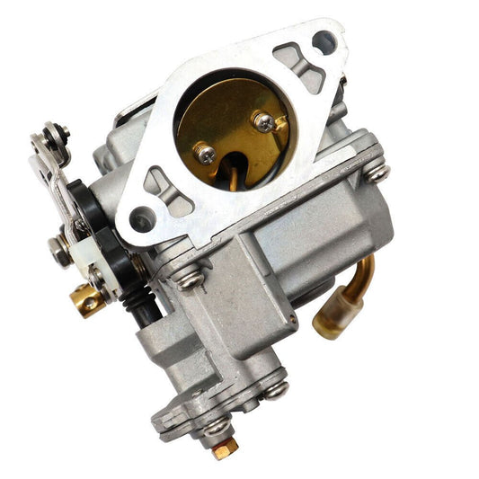
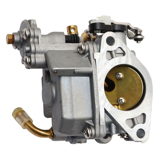
▶Fig. 5 - Carburetor (32 parts)

| Ref | OEM Part # | Part Name |
|---|---|---|
| 1 | 13200-97J50 | Carburetor Assembly |
| 2 | 13236-97J30 | Main Nozzle |
| 4 | 13371-97J00 | Needle Valve |
| 5 | 13250-97J00 | Carburetor Float |
| 6 | 13254-97J00 | Float Pin |
| 7 | 13268-97J30 | Spring |
| 8 | 13251-97J00 | Float Chamber Gasket |
| 9 | 13245-97J00 | Float Chamber |
| 10 | 13249-97J00 | Gasket |
| 11 | 13247-97J00 | Screw |
| 12 | 13268-97J10 | Spring |
| 13 | 13616-97J00 | Screw |
| 14 | 13267-97J00 | Screw (NLA) |
| 16 | 13267-97J10 | Screw |
| 17 | 09493-27L01 | Pilot Air Jet #135 |
| 18 | 09493-29004 | Pilot Air Jet #145 |
| 19 | 13249-97J10 | Gasket |
| 20 | 13248-97J00 | Plate (NLA) |
| 21 | 13268-97J20 | Spring |
| 22 | 13534-97J10 | Screw |
| 23 | 13267-97J20 | Screw (NLA) |
| 24 | 13125-97J00 | Carburetor Gasket |
| 25 | 13413-97J10 | Choke Rod |
| 26 | 13436-91J00 | Choke Rod Connector |
| 27 | 13631-91J00 | Choke Knob |
| 28 | 09103-06522 | Bolt |
| 45672 | 09492-32011 | Pilot Jet #32 |
| 45703 | 09492-34004 | Pilot Jet #34 |
| 45717 | 09491-60014 | Main Jet #60 |
| 45718 | 09491-62009 | Main Jet #62 |
| 45719 | 09491-64003 | Main Jet #64 |
| 45731 | 09492-36L01 | Pilot Jet #36 |
▶Fig. 6 - Fuel Pump (13 parts)

| Ref | OEM Part # | Part Name |
|---|---|---|
| 1 | 15100-97J00 | Fuel Pump Assembly |
| 2 | 15192-97J00 | Replaced by 15192-97JL0 |
| 3 | 15191-97J20 | Fuel Hose (Cock to Pump) (NLA) |
| 4 | 18498-94J31 | Hose Protector (12x15x390) (NLA) |
| 5 | 18498-97J00 | Hose Protector (12x15x260) (NLA) |
| 6 | 59412-91J00 | Fuel Hose Clip |
| 7 | 09401-10412 | Clip |
| 8 | 01550-06257 | BOLT |
| 9 | 08310-00067 | Nut |
| 10 | 15115-97JL0 | Fuel Pump Bracket |
| 11 | 44421-13ER0 | Hose (5x10x600) |
| 12 | 09493-38001 | Air Jet# 190 (NLA) |
| 13 | 15821-97J00 | Hose Protector (16x20.5x80) (NLA) |
▶Fig. 7 - Water Pump (10 parts)

| Ref | OEM Part # | Part Name |
|---|---|---|
| 1 | 17410-97JL1 | Water Pump Case |
| 2 | 09280-33005 | O-Ring |
| 3 | 09116-06232 | Bolt (6x30) |
| 4 | 17415-97J00 | Water Pump Case Grommet |
| 5 | 17461-97JM0 | Water Pump Impeller |
| 6 | 09202-02006 | Pin |
| 7 | 17471-97JL0 | Water Pump Plate |
| 8 | 17472-97JL0 | Water Pump Plate Gasket |
| 9 | 17561-97JM0 | Water Tube (S) |
| 10 | 17563-97J10 | Water Tube Grommet |
▶Fig. 8 - Recoil Starter (13 parts)

| Ref | OEM Part # | Part Name |
|---|---|---|
| 1 | 18100-97JM0 | Recoil Starter Assembly |
| 2 | 18120-97J00 | Reel (NLA) |
| 3 | 18130-97J00 | Ratchet Set |
| 4 | 18142-04410 | Spiral Spring |
| 5 | 18210-97J00 | Starter Grip |
| 6 | 99000-81157-50M | Rope (NLA) |
| 7 | 18211-97J00 | Starter Pulley (NLA) |
| 8 | 01550-06207 | BOLT |
| 9 | 01550-06357 | BOLT |
| 10 | 69711-91J10 | Label S.I.G.P. |
| 11 | 61472-93E20 | Recoil Starter Label (NLA) |
| 12 | 61493-97J00 | Clearance Label (NLA) |
| 13 | 61494-97J00 | Oil Label (NLA) |
▶Fig. 9 - Oil Pump (4 parts)

| Ref | OEM Part # | Part Name |
|---|---|---|
| 1 | 16131-91J00 | Oil Pump Inner Rotor |
| 2 | 16132-91J00 | Oil Pump Outer Rotor |
| 3 | 16161-97J10 | Oil Pump Rotor Plate |
| 4 | 02142-0510B | SCREW |
100-Hour / Annual Service Checklist
Regular maintenance keeps your Suzuki DF 2.5S running reliably season after season. Most of these tasks can be performed with basic tools and the factory service manual.
- Replace water pump impeller and inspect wear plate
- Change engine oil and oil filter (check drain plug washer)
- Replace spark plugs and check ignition timing
- Drain and refill lower unit gear oil; inspect for water contamination
- Inspect fuel lines, primer bulb, and fuel filter for deterioration
- Check and replace sacrificial anodes (zinc or aluminum)
- Inspect propeller for damage; check shaft seal and cotter pin
- Check valve clearance (refer to service manual for specifications)
- Lubricate all grease points (steering, tilt tube, shift linkage)
- Inspect control cables and throttle/shift linkage for smooth operation
- Pro Tip: Always flush the engine with fresh water after saltwater use — even a quick 10-minute flush significantly extends component life.
- Pro Tip: Use fuel stabilizer in the tank before winter storage, and fog the cylinders to prevent internal corrosion during extended periods of non-use.
Recently Viewed Products
Example product title
- $19.99
- $19.99
- Unit price
- per
Example product title
- $19.99
- $19.99
- Unit price
- per
Example product title
- $19.99
- $19.99
- Unit price
- per
Example product title
- $19.99
- $19.99
- Unit price
- per
Example product title
- $19.99
- $19.99
- Unit price
- per
Example product title
- $19.99
- $19.99
- Unit price
- per
Example product title
- $19.99
- $19.99
- Unit price
- per
Example product title
- $19.99
- $19.99
- Unit price
- per
Example product title
- $19.99
- $19.99
- Unit price
- per
Example product title
- $19.99
- $19.99
- Unit price
- per
- Choosing a selection results in a full page refresh.